Al-Quds Project
Al-Quds Project
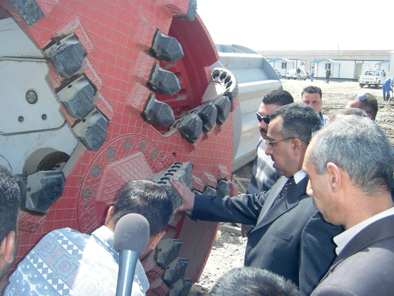
conveyor line/hidden pits jacking method
Our company has constructed a sewage line (heavy water) along AL QUDS Street and a length of 5000 m. starting from Hamza Square to 83 Square and this transport line Intakes pumps and discharges heavy water and rainwater for the sectors of Sadr Clity and Jamila neighborhood and alleviate the bottlenecks In the sewage systems and then drainage and connectivity on the main zibeline line and helps the vertical pumping station In the area of Habible by withdrawing part of the amount of water entering It and then pump Into zibeline main line, In addition to the establishment of rain gully to draw surface water on The length of AL-Quds Street and according to the design plans.
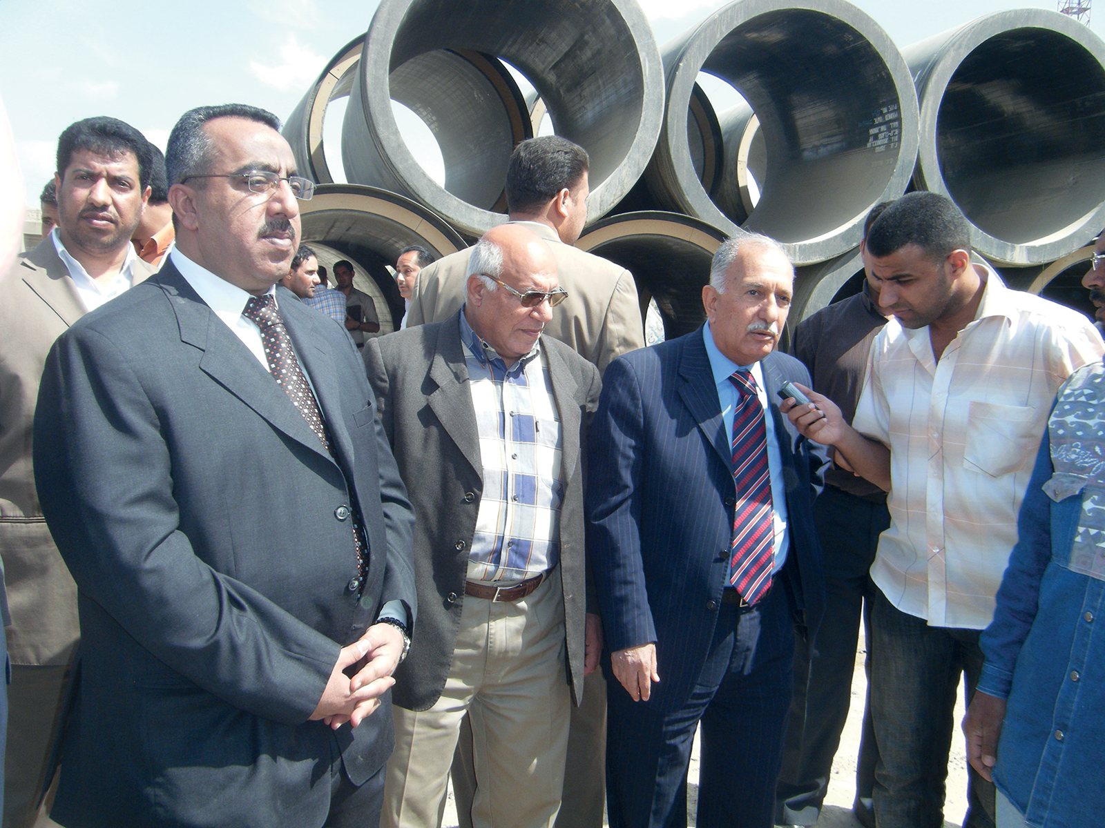
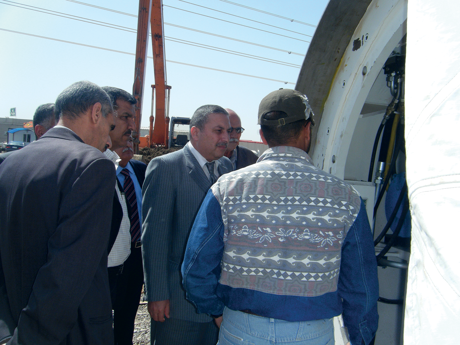
Field visits
- Visit of leghdad Mayor - Dr. Saber Al-Issawi.
- Visit of Mr. Under Secretary of Baghdad Mayor for Technical Affairs-Eng. Ibrahim Mustafa.
- Visit of The Director General of the Bagindad Sewerage Department/Visit of the Former Director General of the Baghdad Seweraga Department.
- Visit of Mr. Assistant Director General of the Baghdad Sewerage Department/Visit of Mr. Deputy Chairman of the Baghdad Provencal Council.
- Visit of The Head of The Baghdad Services Authority.
Work details
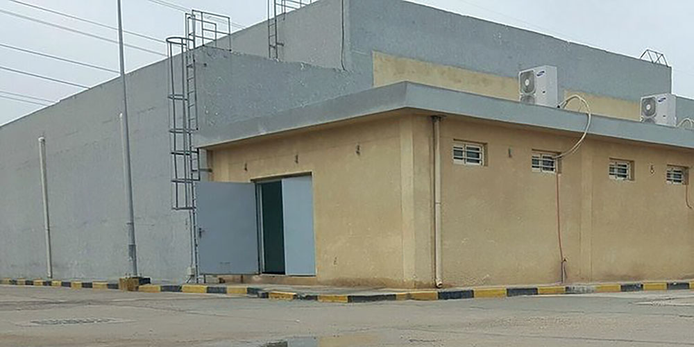
First: the vertical station of AL-Quds Street (Habibiya 2):
The station was constructed with a depth of 14 meters below the natural ground level and an area of 22,500 square meters with a pumping capacity of up to 53,000 cubic meters per hour.
Second: line carrier
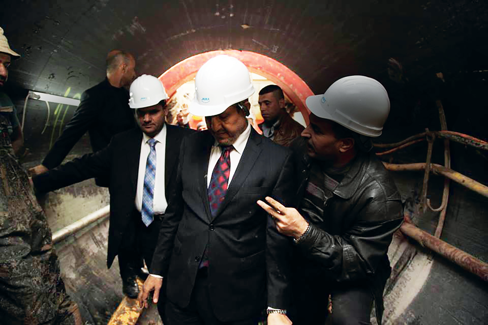
Our company has implemented the main carrier line with a diameter of 2000 mm by the hidden drilling method (JACKING MACHINE) and the length of (5000 m) and includes the line inspection basin in special sizes (large) and with 20 inspection basins have been connected all the substations and rainwater networks located within the line of the main conveyor line implemented.
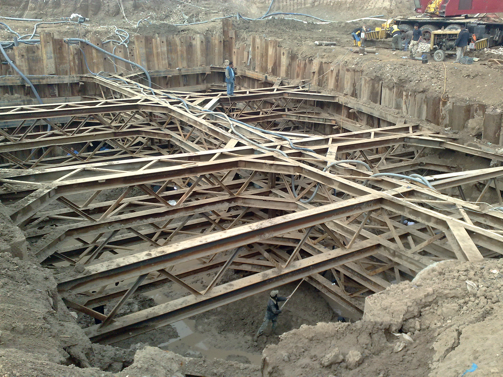
TUNNELS WORKS & PROJECTS
- The length of the tunnels varies from basin to basin and according to the charts ranging from (180 to 250) meters.
- The tunnel depths range from (6 to 10) meters.
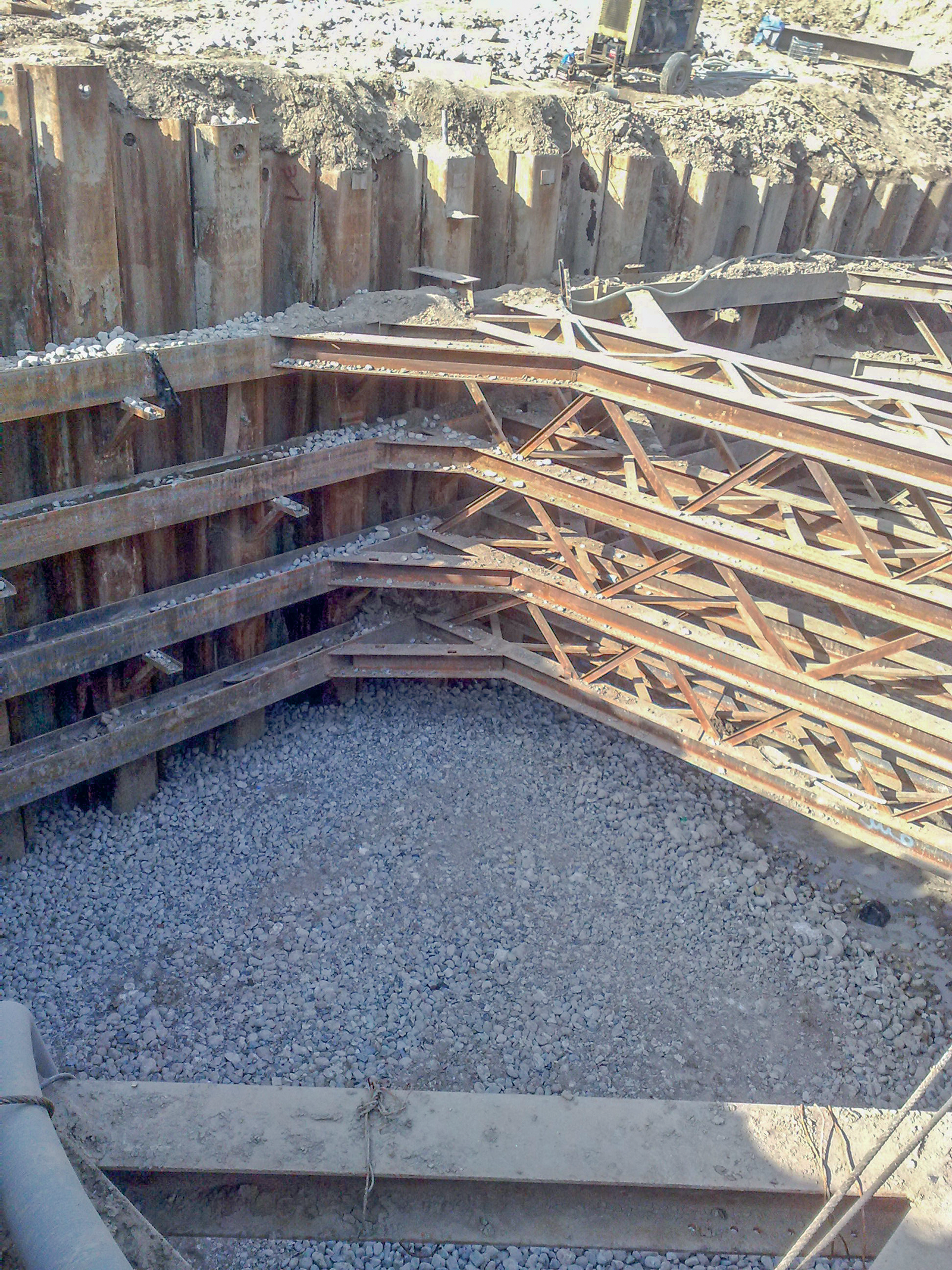
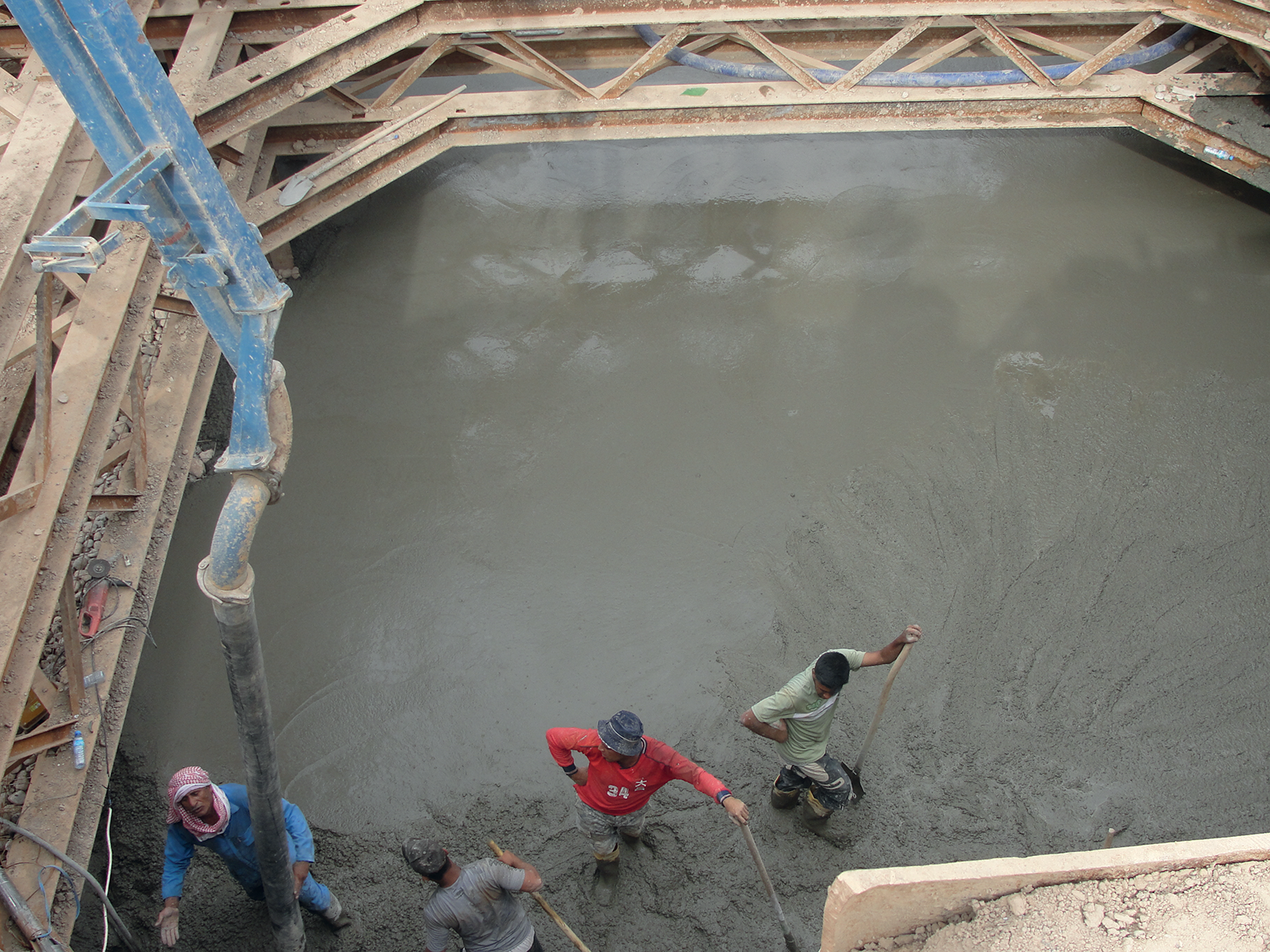
- casting concrete with thickness 75 cm at the basement of the basin.
- Dropping and installation of the base (slider) of the jacking machine.
- Installation the supporting reinforced concert wall behind the machine with and then drop and install the machine's jacks on it.
- cast 50 cm at the exist side of the line.
- The average length of jacking pipes is (5 to 6) pipes per day.
DEVELOPMENT OF SITE WORKS AND PROJECTS
The company manufactured a steel base for the machine in addition to the base previously existing with the machine, and this would reduce the time period in transferring the machine from one inspection basin to another upon completion of drilling
THE WORK IS DEVIDED:
First: Work of preparing inspection basins and laying pipes.
- choosing the basin location acording to the plan and the sheet pile installation and dewatering.
- supporting the sheet piles with horizontal (H beam) sections, adding subgrade, compacted it and adding the blinding.
- Lowering the slider part of the machine, determining the entry and exit opening of the machine, and preparing the attachments for the machine before the process of lowering the machine. Laying the jacking machine, setting the rear jacks of the machine.
- Lowering the drilling machine and placing the back gaskets of the machine and other accessories. The first stages of laying concrete into the basin and the final stages as well.
- Lowering the pipes and lifting the dust resulting from the drilling process and laying the pipes.
- The process of jacking machine exit from the exit shaft and the process of pressing pipes for the inspection basin and preparing molds for inspection basins according to the plans.
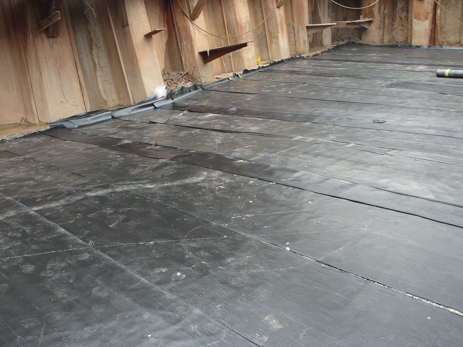
- The initial stages of pouring the inspection basin (the first lifting) and the final stages of pouring the inspection basin, making the neck and coating with asphalt (flankot) from the outside.
- Covering manholes with P.V.C during the casting process and lifting the iron pillars after preparing the inspection basin and treating the pipes from the inside by thermal air cauterization.
Second: Lifting Station.
- installation of steel piles, dewatering, drawing underground water, and digging the station.
- supporting the steal piles with horizontal section of (H beam) and make another support from insidealso with (H beam) sections and befor the compacted the subgrade.
- Pour the blinding layer and felt brushes and pour the foundation.